
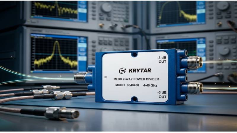
A signal is split two ways. One output feeds a receiver under test. The other feeds a monitoring instrument that gets disconnected partway through the session, and the open connector is left as it is.
Readings on the first path shift. Not by much, and not uniformly across frequency, but enough that a marginal measurement crosses a threshold. The disconnected port is treated as inactive because nothing is connected to it.
A splitting network does not have inactive ports. Every port participates in the network’s behavior, and what is attached to one output affects what appears at the other.
Ports Are Coupled Through the Network
A splitting device divides input energy between outputs through a defined internal structure.
That structure determines the relationships between all ports, not just between input and each output. The two outputs have a relationship to each other, described by isolation, and each has a relationship to the input.
An open or short at one output reflects energy back into the network. That reflected energy redistributes according to the internal structure, appearing partly at the input and partly at the other output.
Where isolation between outputs is finite, some of it arrives at the other output and adds to the signal there, with a phase depending on the electrical length involved.
Reflections Return Frequency-Dependent Errors
The path from one output, back through the network, and out the other output has an electrical length.
Phase accumulated over that length varies with frequency. At some frequencies the reflected contribution adds to the intended signal; at others it subtracts.
The result is a ripple in the amplitude and phase at the working output as frequency changes. Its magnitude depends on the reflection at the disconnected port and on the isolation between outputs.
An open connector reflects nearly all incident energy, so the reflection is close to full magnitude. The isolation figure then sets how much reaches the other output.
Isolation Determines How Much Leaks Through
Isolation between outputs is a published specification and varies with frequency.
Resistive dividers offer limited isolation by design, since the outputs are connected through resistances and energy passes between them readily.
Reactive designs achieve higher isolation through an internal balancing element that absorbs energy arriving from a mismatched output rather than passing it to the other. A two way power divider built this way maintains isolation across its specified band, with the figure degrading toward the band edges.
Higher isolation reduces the effect of a mismatched output on the other, which is precisely why isolation is specified.
No practical device offers infinite isolation, so no design fully eliminates the interaction.
Input Match Degrades Simultaneously
The reflection from an unterminated output also travels back toward the input.
The device’s input reflection coefficient is specified with all outputs properly terminated. Leaving one open changes it, typically for the worse.
That degraded input match then interacts with the source’s own mismatch, producing the source-load interaction that limits measurement accuracy.
A source characterized against a well-matched load behaves differently when driving a network with an open port, and the difference appears as a level shift at the working output.
Termination Restores the Design Condition
A load matched to the system impedance absorbs incident energy rather than reflecting it.
Fitting one to an unused output eliminates the reflection and returns the network to the condition its specifications describe.
Terminations carry their own reflection coefficient specification, which is not zero. A precision termination presents a small reflection; a general-purpose one presents more.
Power rating matters. A termination on the output of a splitting network dissipates a share of the input power, and one rated below that level will overheat, changing its impedance as it does so and eventually failing.
Frequency range matters. A termination specified to a lower frequency than the signal presents an unknown and generally poor match above its range.
Connector Torque and Condition Affect the Result
A termination fitted loosely does not present its specified impedance.
Precision connector interfaces depend on consistent mechanical contact, and torque specifications exist because the electrical characteristics vary with it.
Contamination on either mating surface introduces a discontinuity. Inspection before connection takes seconds and prevents a measurement compromised by a dirty interface.
Worn interfaces present degraded match. Connectors on frequently used terminations wear, and periodic inspection identifies them before they affect results.
Adapters Between the Termination and the Port Add Error
Where connector series differ, an adapter is required, and it contributes its own reflection.
A between-series adapter can present more reflection than the termination itself, particularly at higher frequencies, which partly defeats the purpose of fitting a precision load.
Terminations are available in multiple connector series, and selecting one matching the port avoids the adapter entirely.
Where an adapter is unavoidable, its contribution belongs in the uncertainty accounting rather than being ignored.
Multiple Unused Ports Compound
In networks splitting more than two ways, several outputs may be unused at once.
Each contributes independently, and the contributions combine with phases determined by their respective path lengths.
The combined effect can be larger or smaller than any single contribution depending on those phases, and it varies with frequency in a pattern that is difficult to predict without measurement.
Terminating all unused outputs is the practical response, and keeping a set of matched terminations with the equipment makes it routine rather than an extra step.
Verification Confirms the Condition
Measuring the working output with the unused port open, then terminated, quantifies the difference.
Where the difference is negligible for the measurement being made, the effort of terminating is confirmed as unnecessary for that case. Where it is not, the measurement has been protected.
Sweeping across the frequency range shows the ripple pattern, which identifies whether the effect is uniform or concentrated at particular frequencies.
Recording the result establishes whether termination is required for that setup rather than leaving it to assumption.
What the Setup Requires
The items are specific and inexpensive relative to the measurement.
A termination for every unused port, matched to the connector series and rated for the power and frequency involved. Its reflection coefficient specification, for the uncertainty budget. The network’s isolation figure across the band in use. Clean, correctly torqued interfaces throughout.
The specifications describe a network with all ports terminated. Any port left open describes a different network, and its behavior is not what was specified.See More